
Innotek Office
Project details
This project involves the renovation and design of the bottom 2 stories of a 4-story commercial building of historic significance in San Francisco's financial district. Emphasis is on code compliance and construction document drafting. The client, Innotek, is a technology company looking to move its main offices into the space.
As part of my Building Codes class at AAU, this project was to be completed from the Programming through the Contract Document phase, with special emphasis on correctly studying and applying building code compliance with the IBC and the local building authority. The project began with learning how to find the correct governing building codes based on site location, and using the respective zoning requirements to compute max square footages and occupancy loads based on those requirements and the building type.
After the parameters for local and IBC code compliance were established, I designed an office that met with program requirements while inspiring an innovative tech environment for the employees.
Area of site | 9000 ft2 |
Status of the project | Complete thru Construction Document Phase |
Tools used | Revit, InDesign, International Building Code |
Building Type &
Zoning Category Analysis
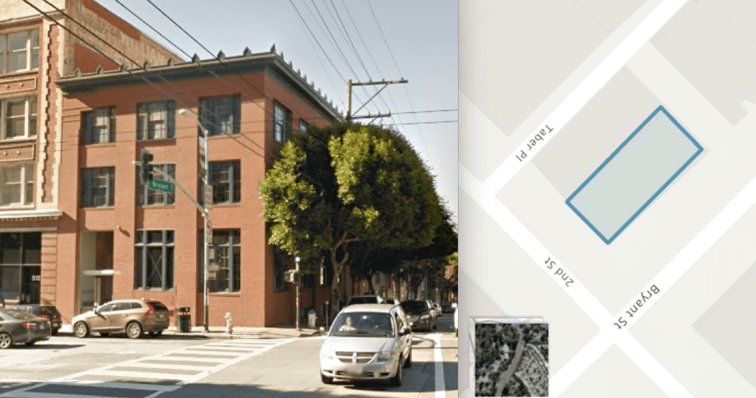
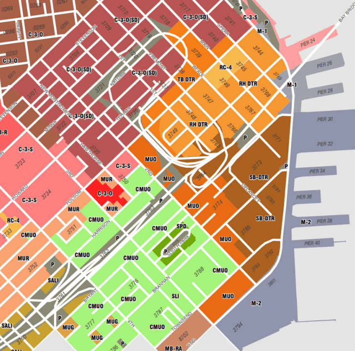
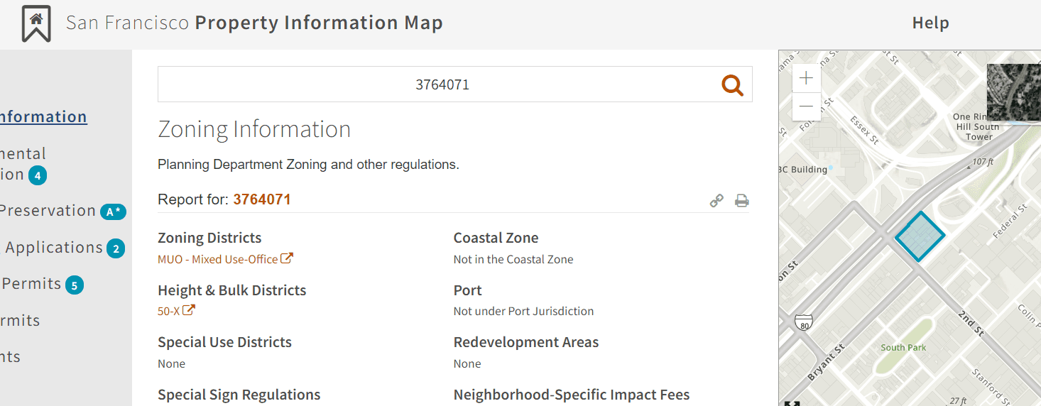
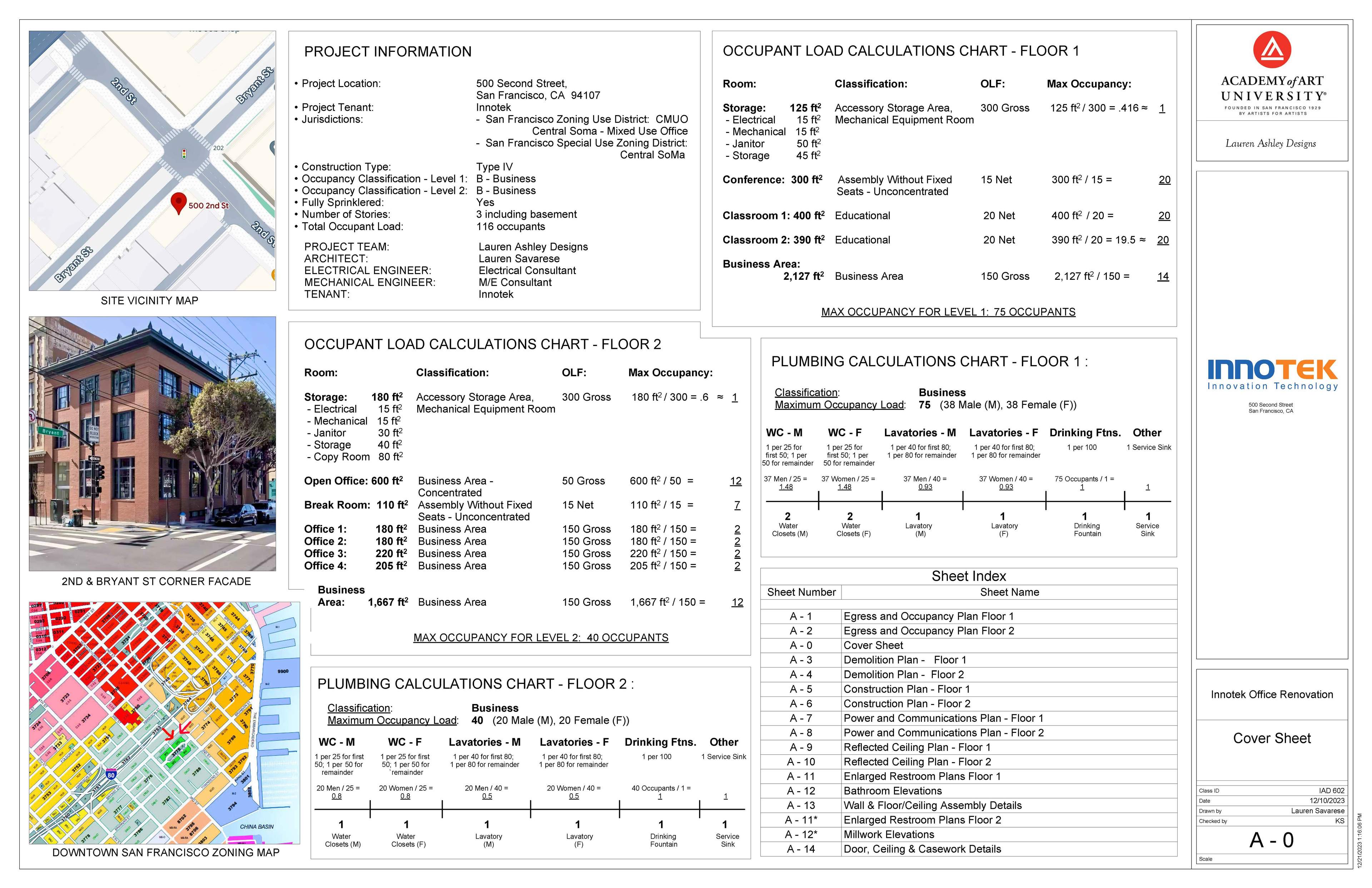
The first step of this project was to examine the site of the existing building, and find the relating San Francisco building and zoning codes. Using sfplanning.org, I was able to find the site's zoning category and district, and ensure the client that their intended use of the building as an office was code compliant. At left is the zoning map of the financial district of San Francisco that I was working from. This project site's zoning district, at 2nd & Bryant St, is CMUO - "Central Soma - Mixed Use Office".
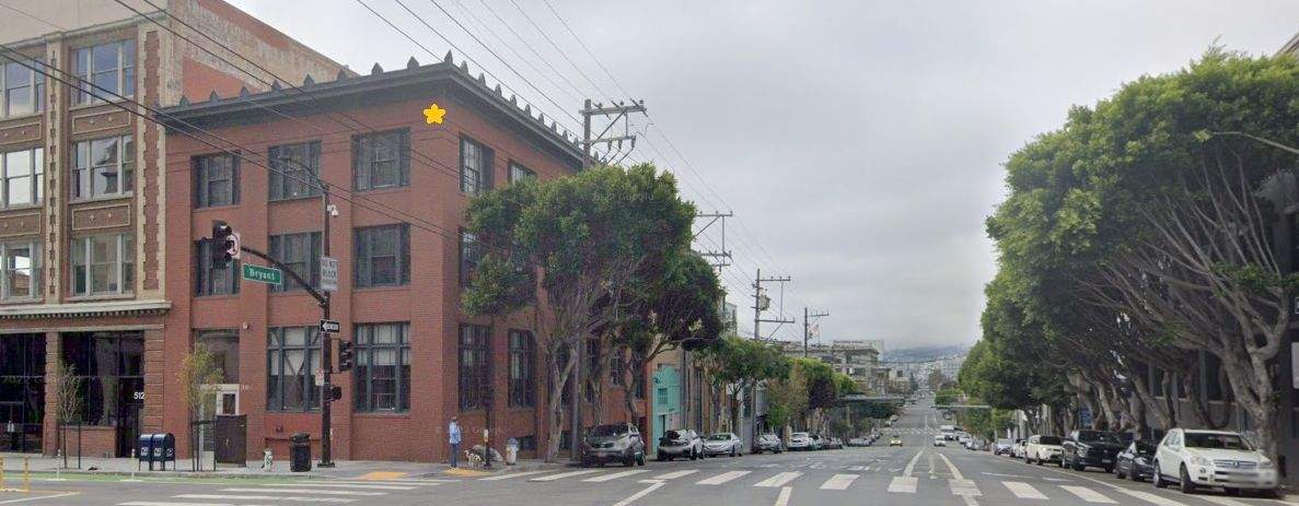
Below, is an image of the existing building's 2nd St. facade and correlating map location.
The next step was to ascertain the building type and occupancy codes. Based on the structure's heavy timber construction, the building is classified as a Type IV.
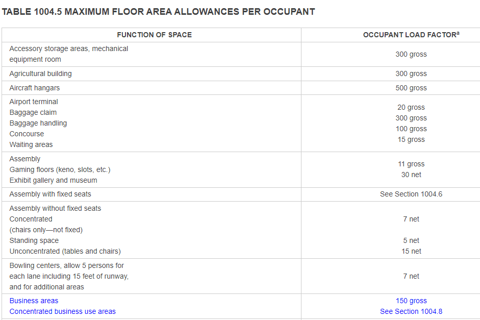
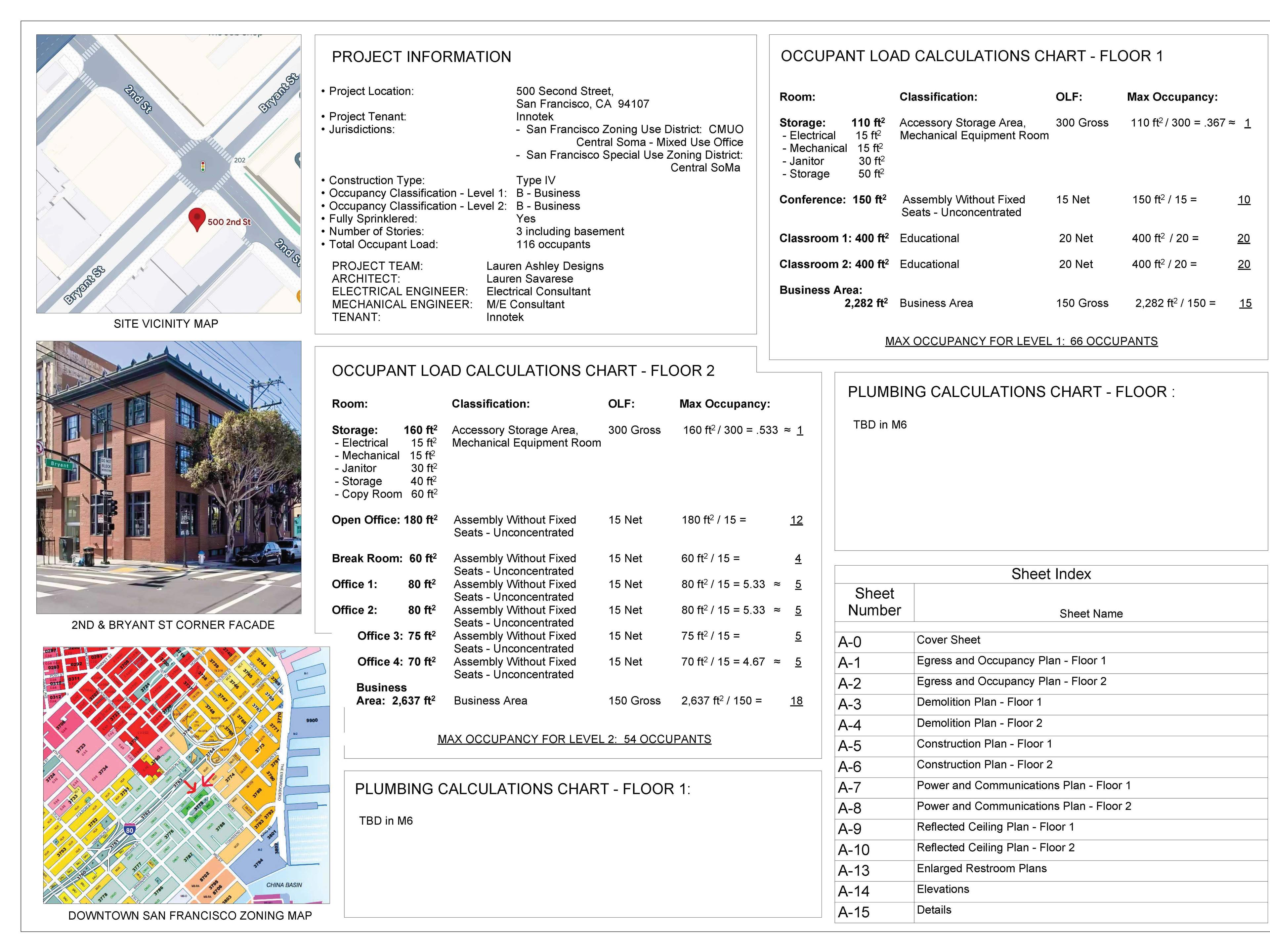
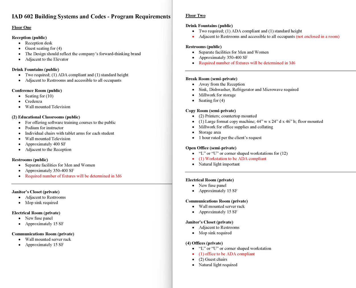
Given a B - Business occupancy classification based on the intended use of the space, I was then able to compute the occupancy loads for Levels 1 & 2 (where the office would go) using the provided programming requirements that outlined the function of each space necessary in the office, along with the minimum square footages of each of these spaces. I outlined these calculations on the cover page of the construction document set, along with other information I had on the project, as seen below.
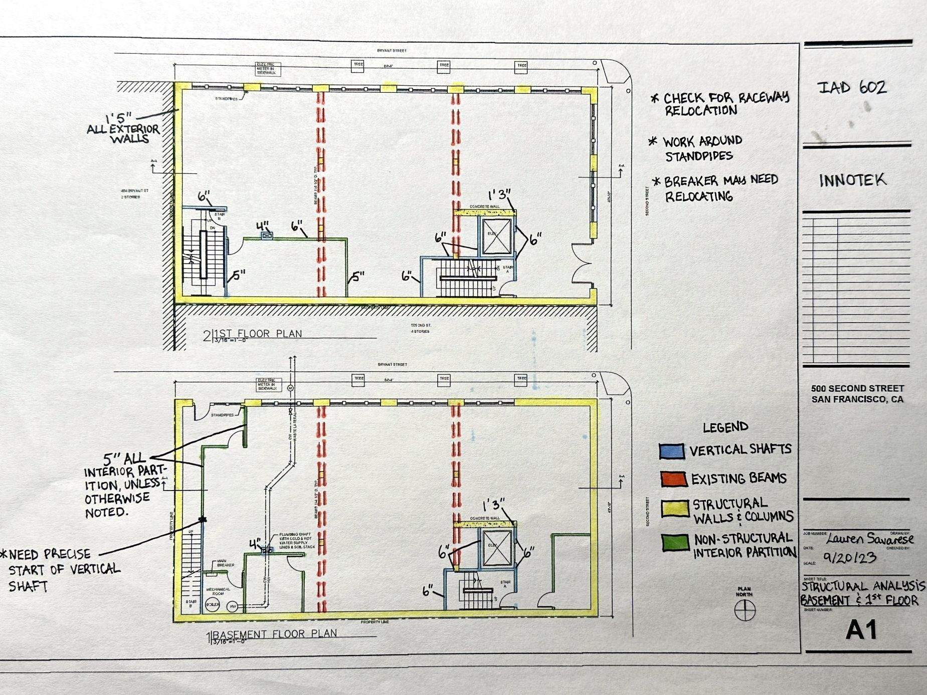
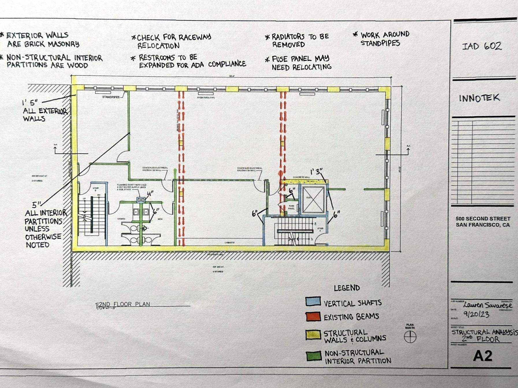
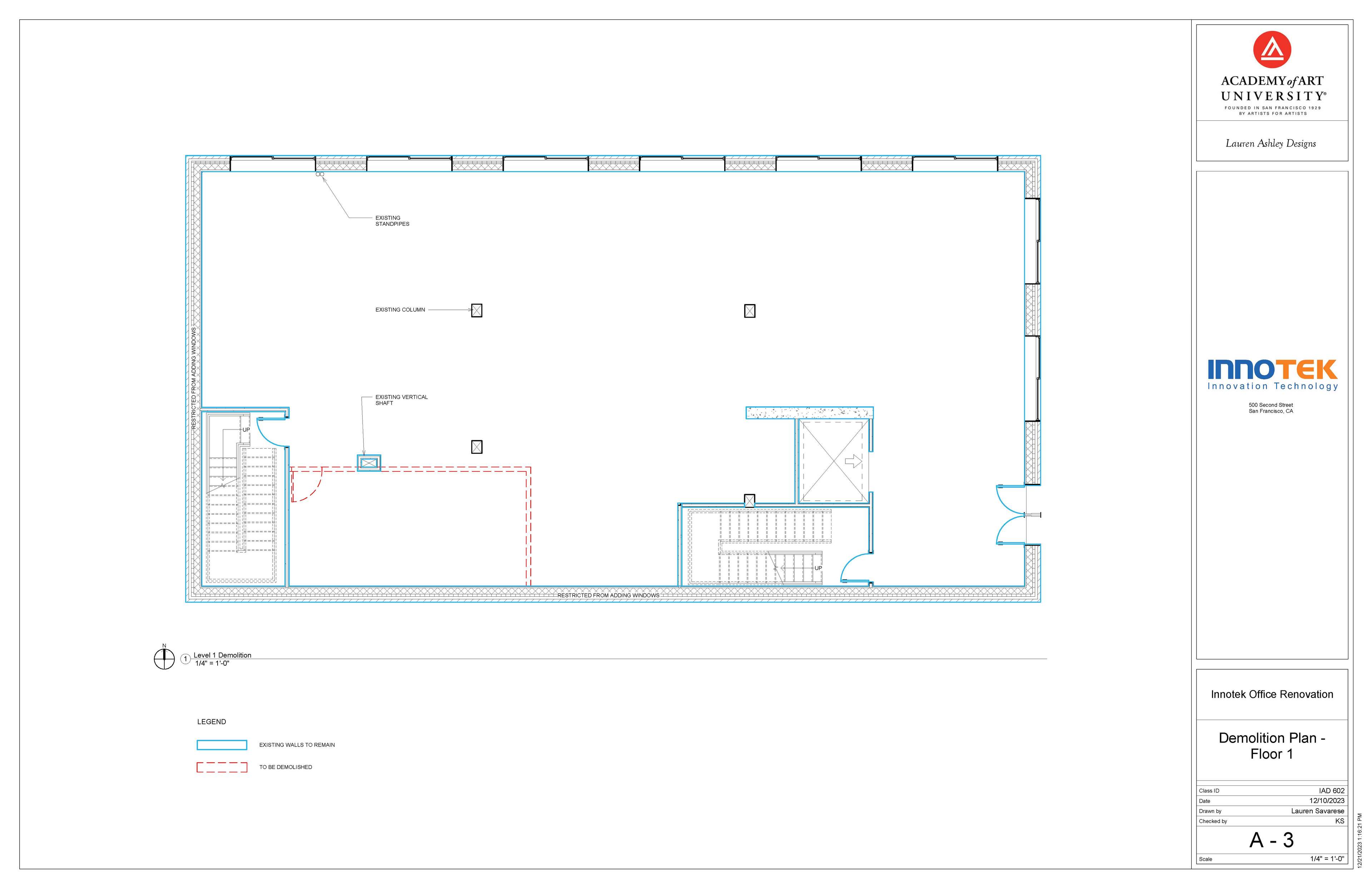
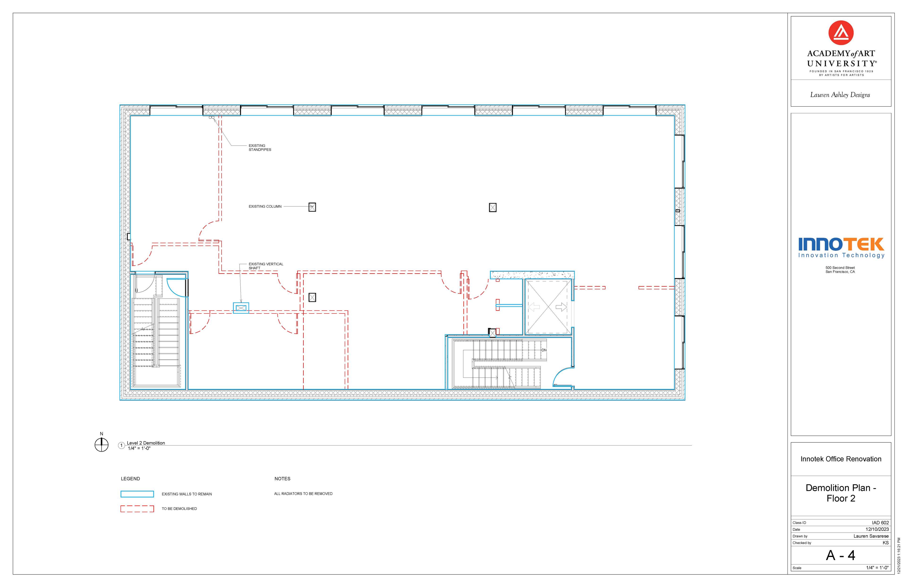
Structural Analysis
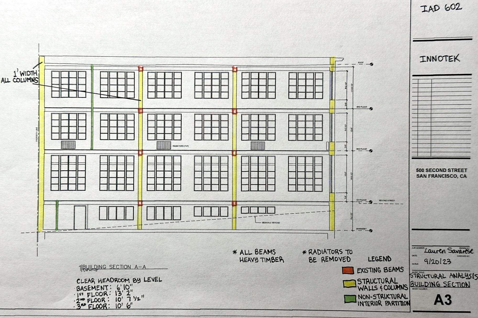
Working from provided construction plans of the pre-existing basement, 1st, and 2nd floors, the next step in this project was to figure out where all immovable and/or structural columns, beams and shafts were located within the building.
Schematic Design 1st Draft
Using the provided program requirements seen at left, and the structural elements realized above, I made my first pass at arranging the various functional spaces through bubble diagramming and blocking; seen below.
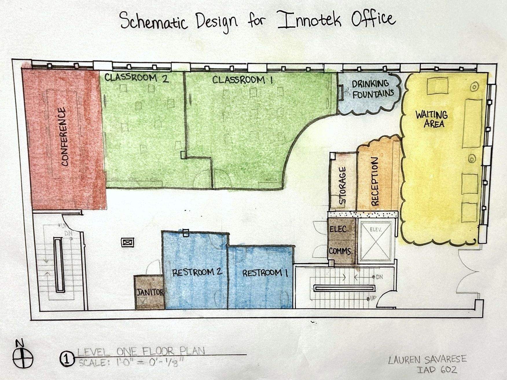
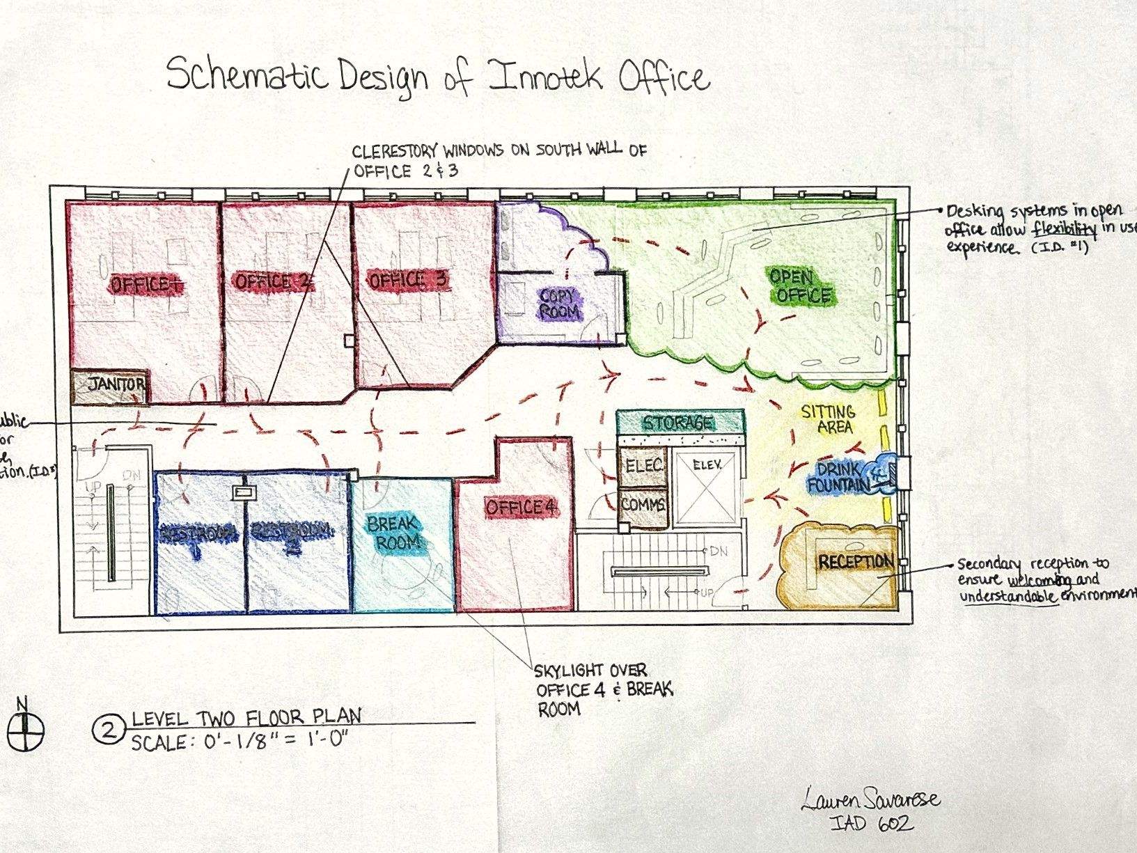
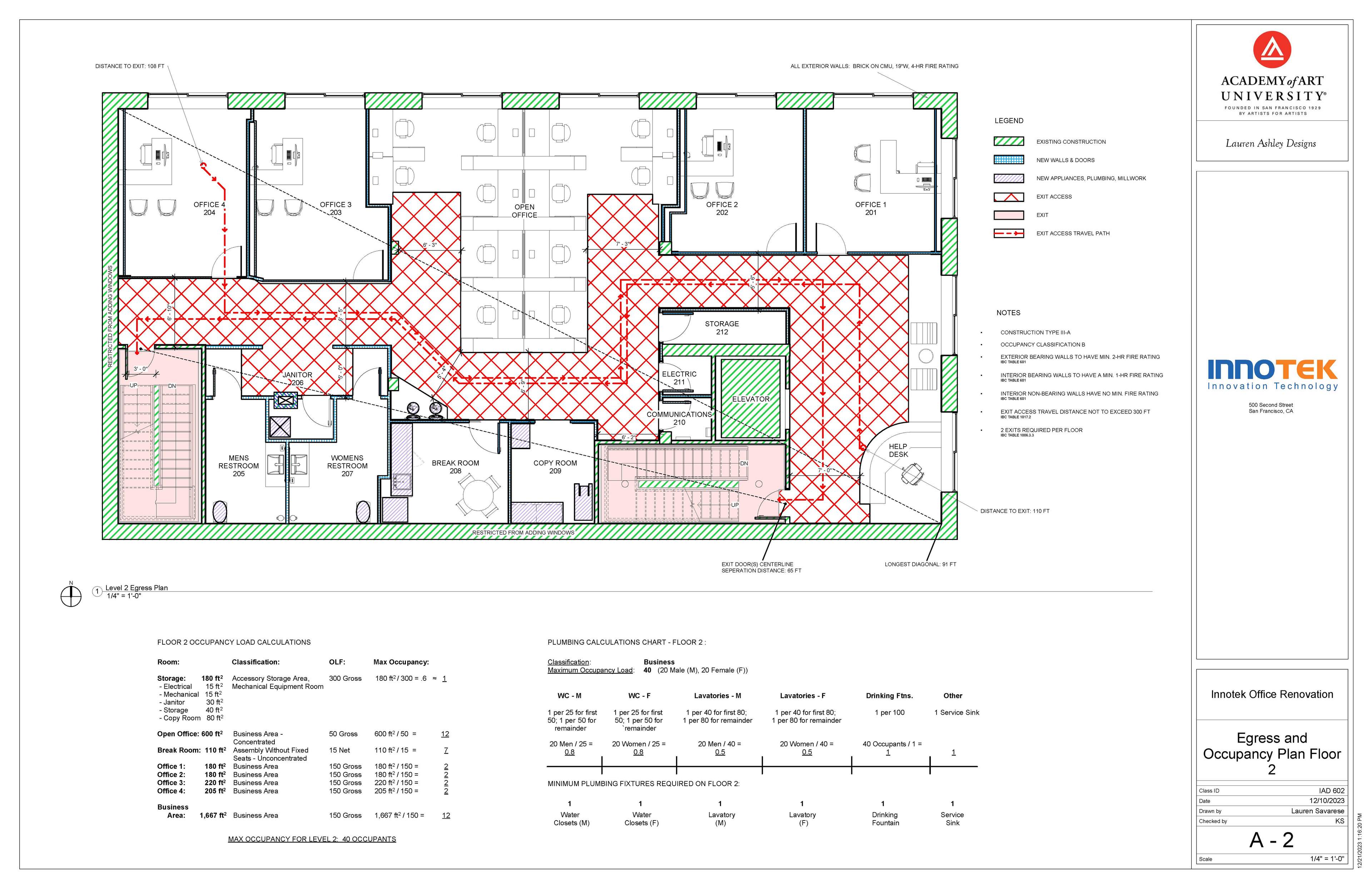
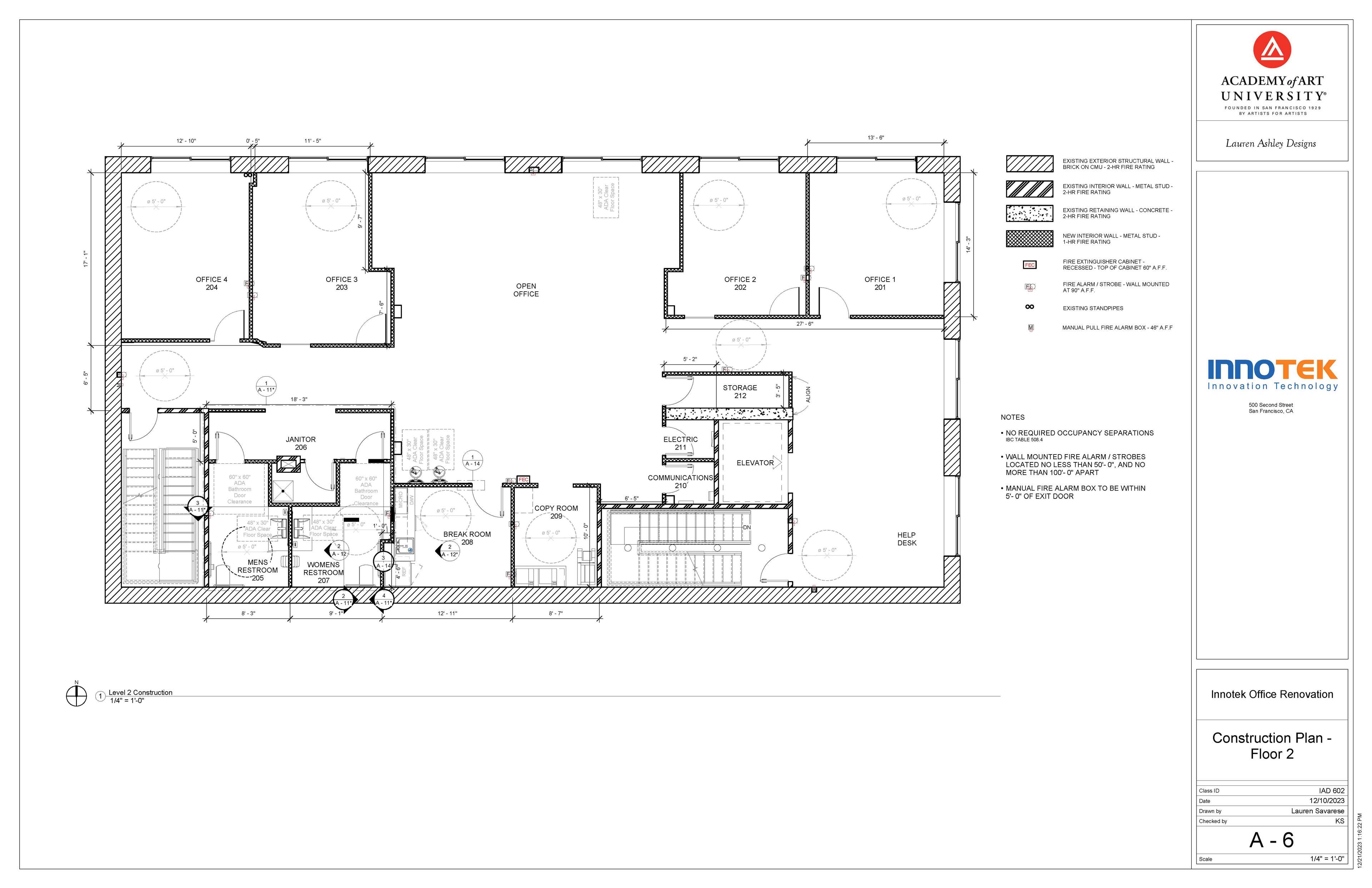
My final design resembled my first floor schematic plan closely, but was tweaked more significantly from my second floor schematic plan. The open office was moved to the center of the floor, and additional partitions were used to hide restroom entry from public circulation more effectively.
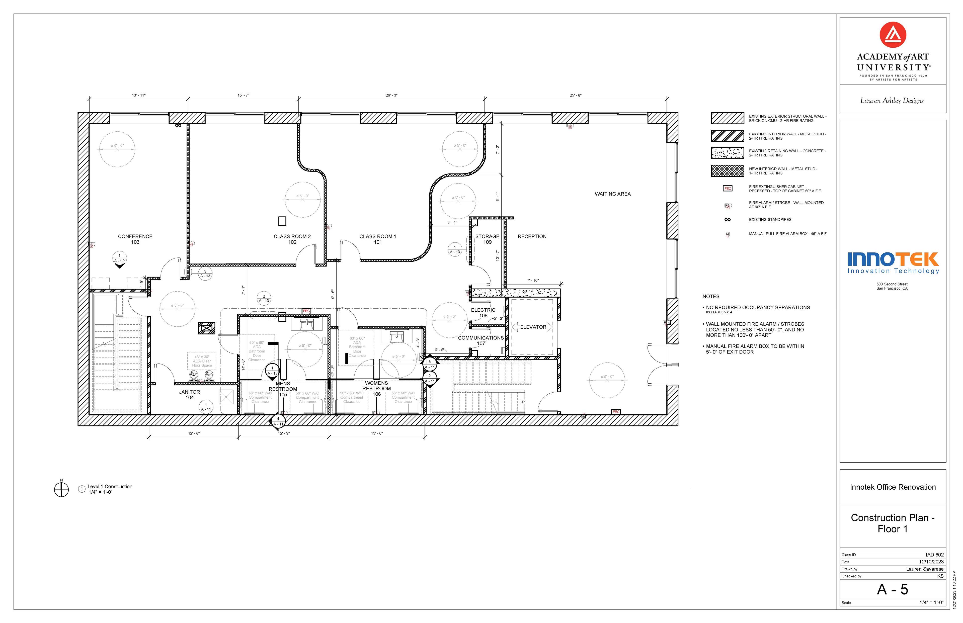
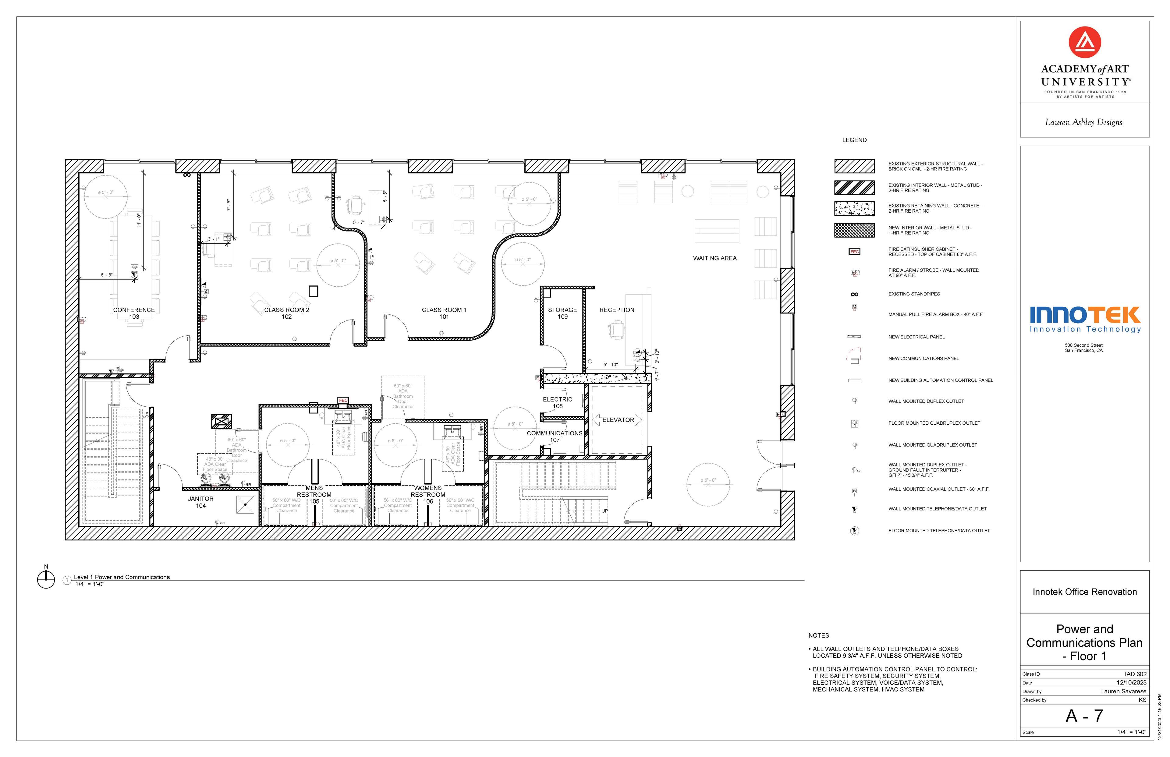
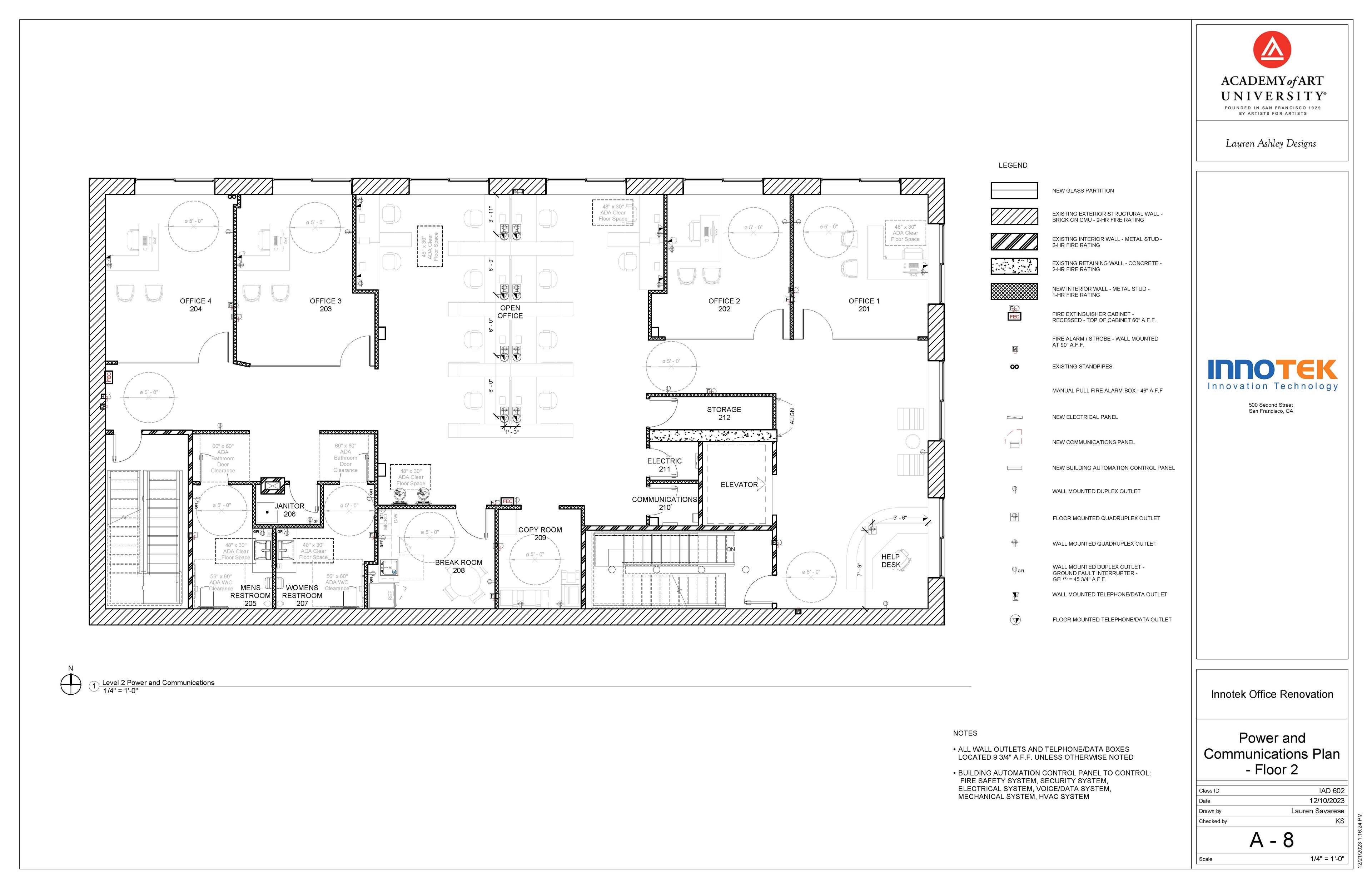
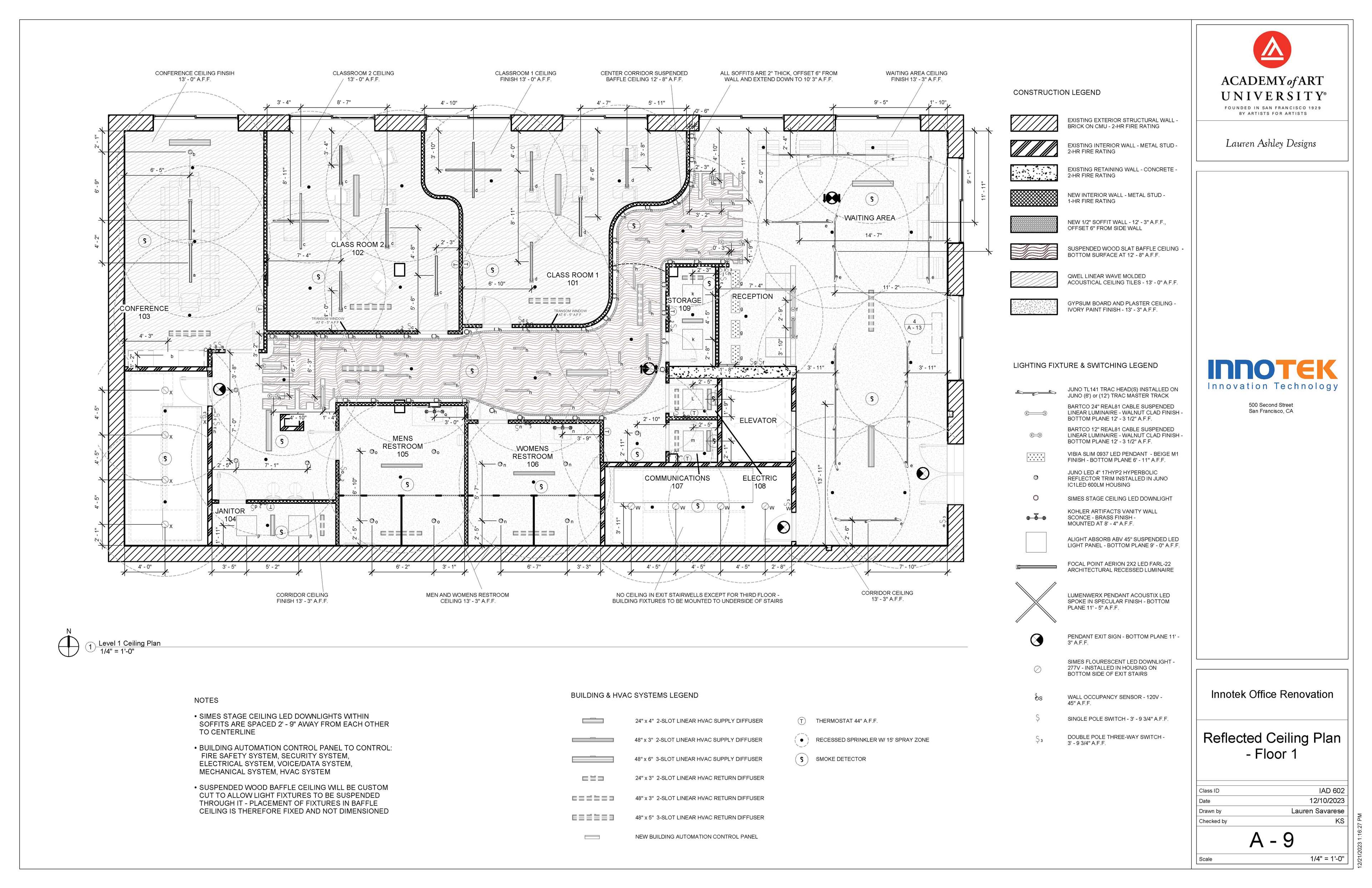
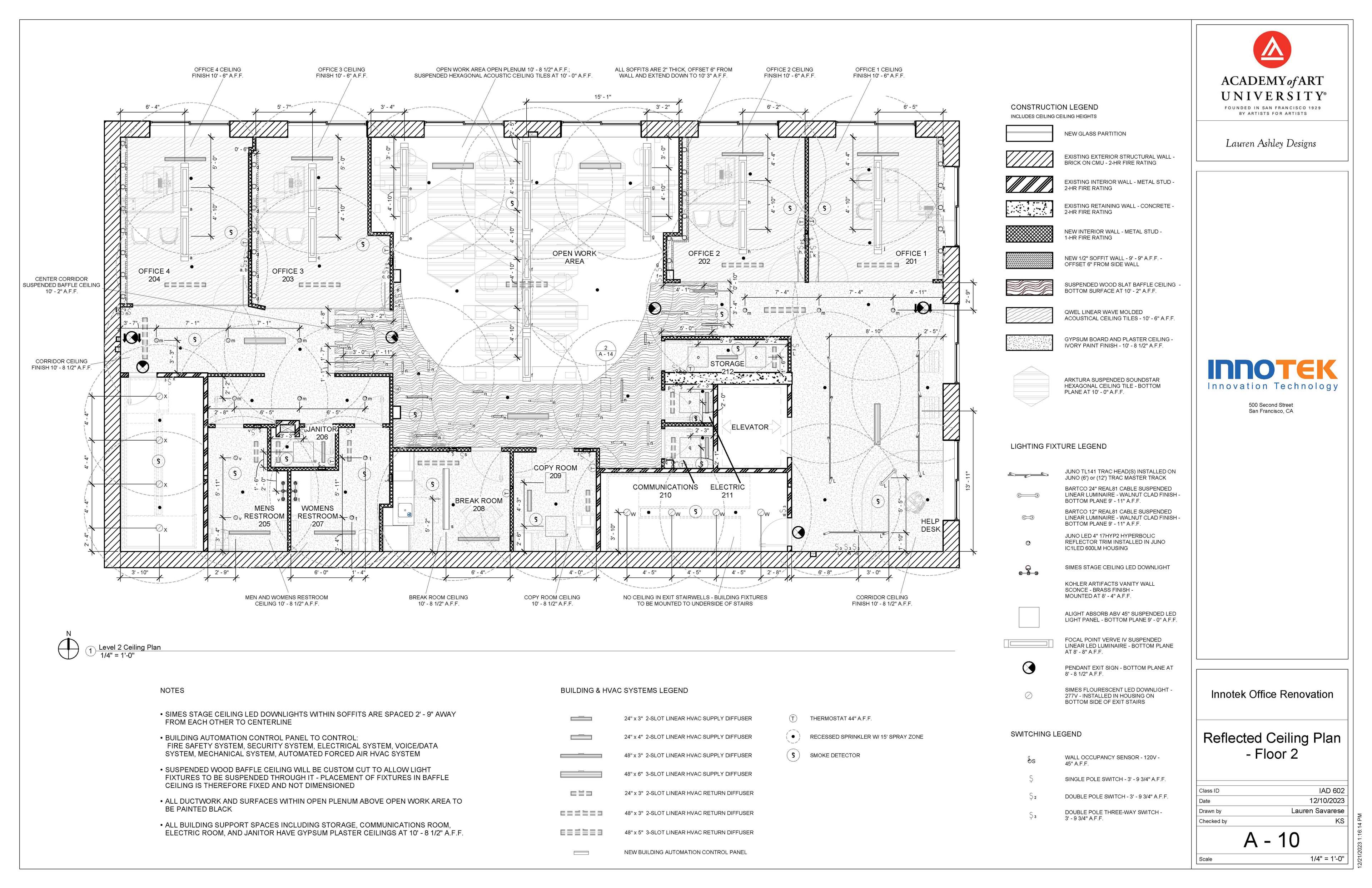
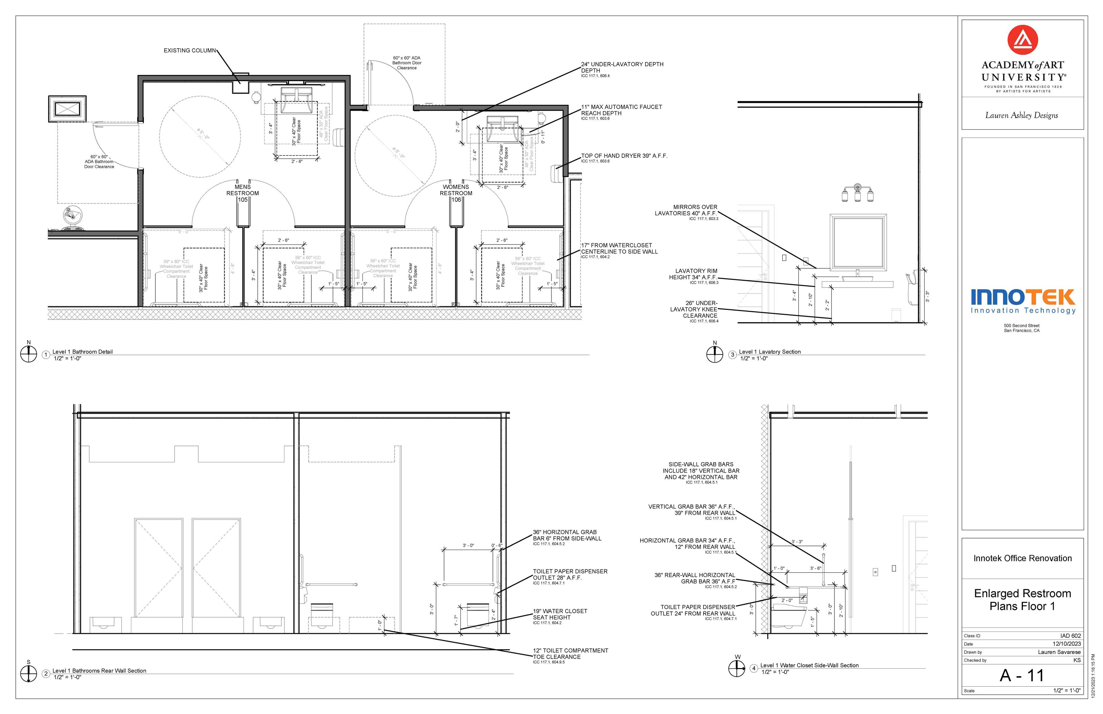
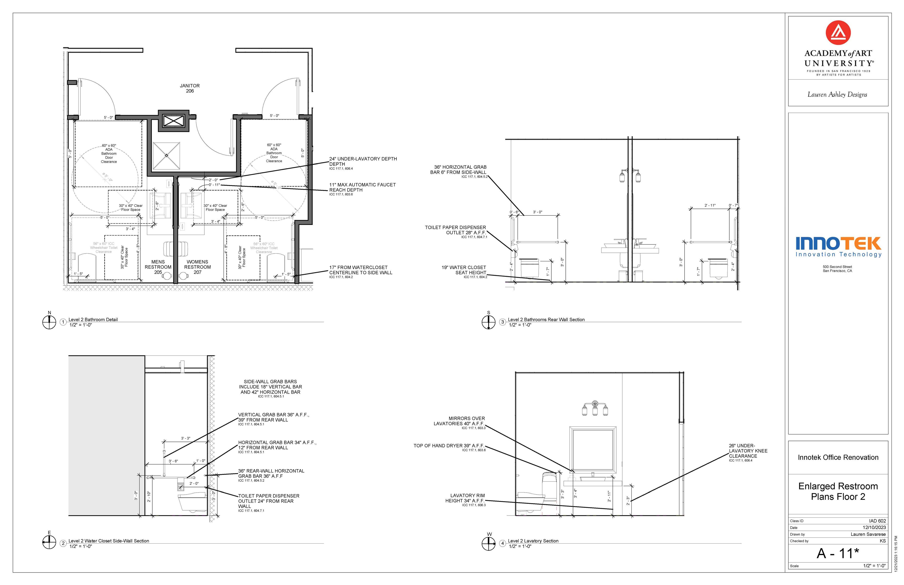
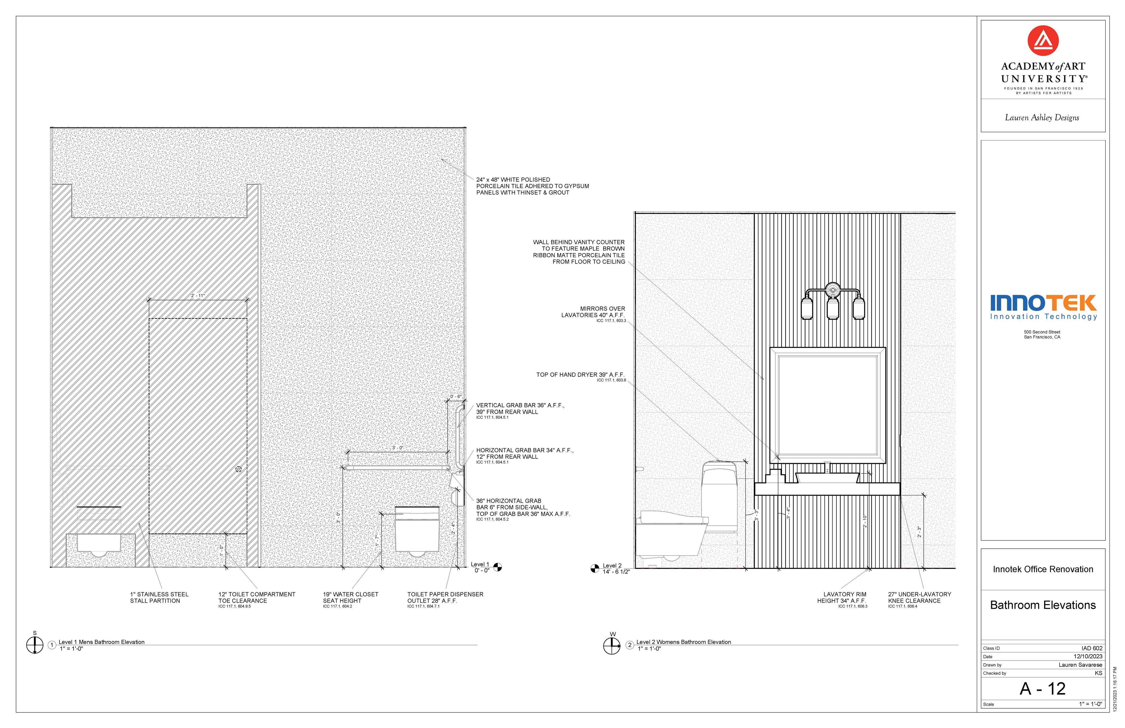
Below is my final construction document set for this project. Each sheet type represents the culmination of a week's worth of code research and design drafts of that particular phase of the project, that was developed through critique from fellow designers and my professor as each design phase progressed.
Construction Documents

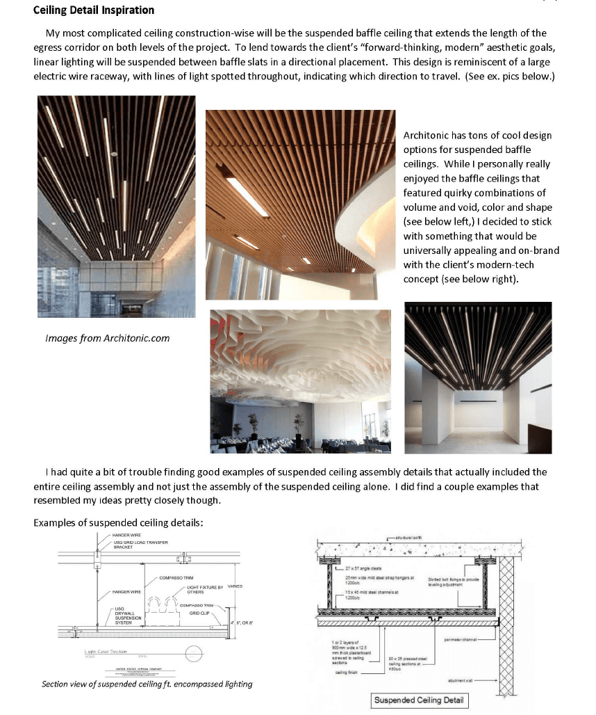
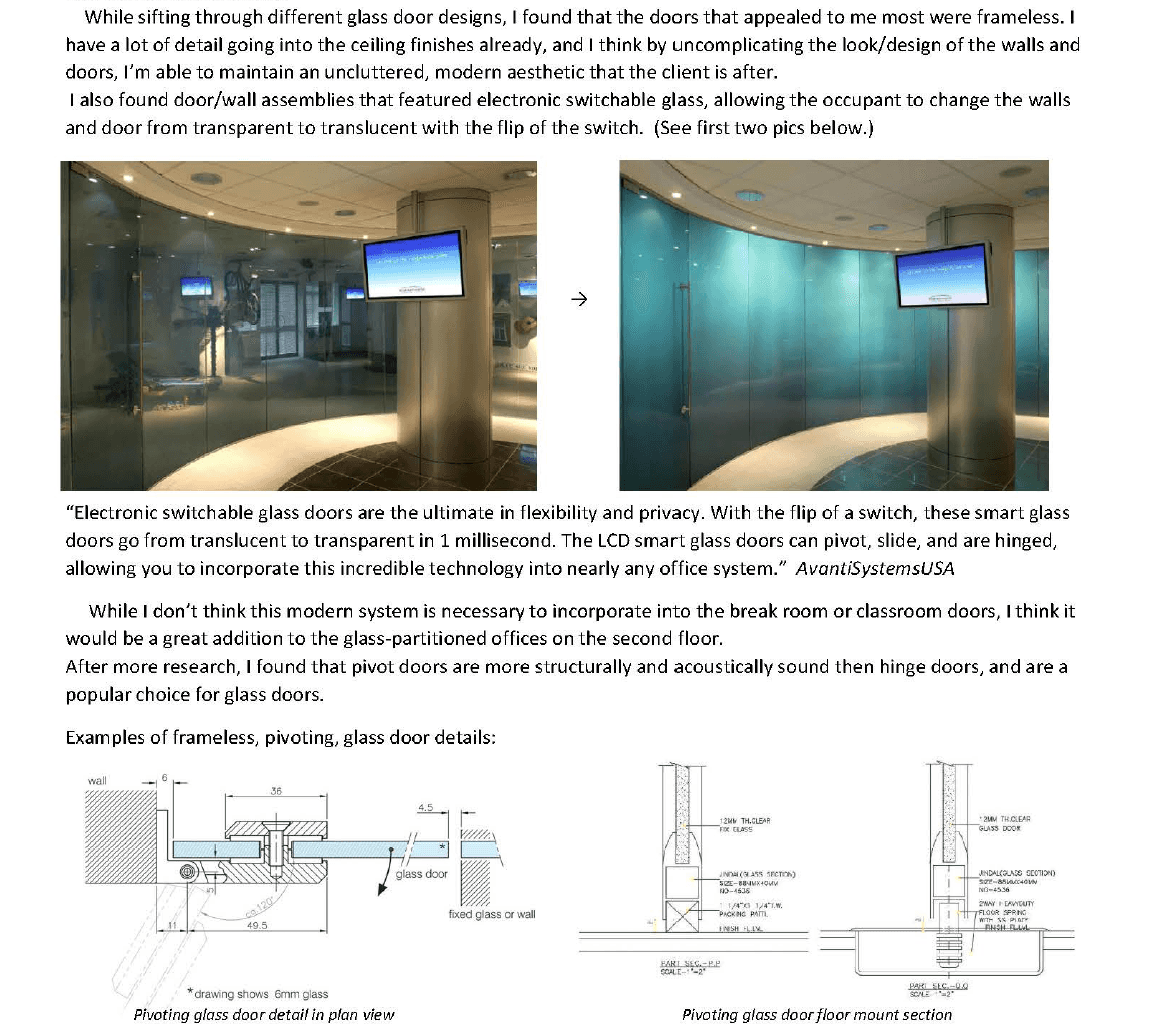
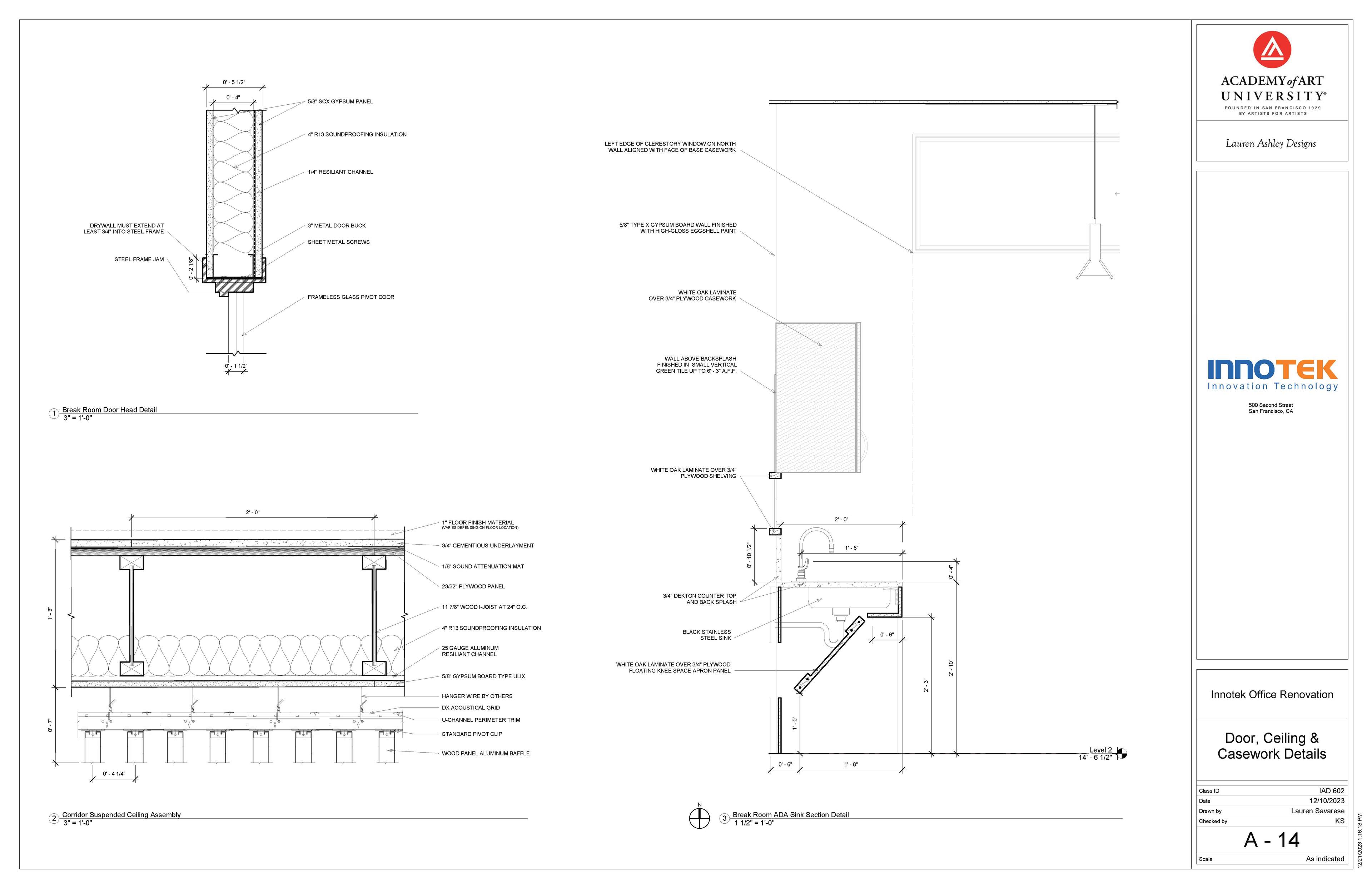
Construction detail documentation was limited one ceiling and one door detail. I researched different kinds of door and ceiling assemblies, and found some styles close to what I wanted that included construction details I could use once I modified them to my specific door and ceiling selection.
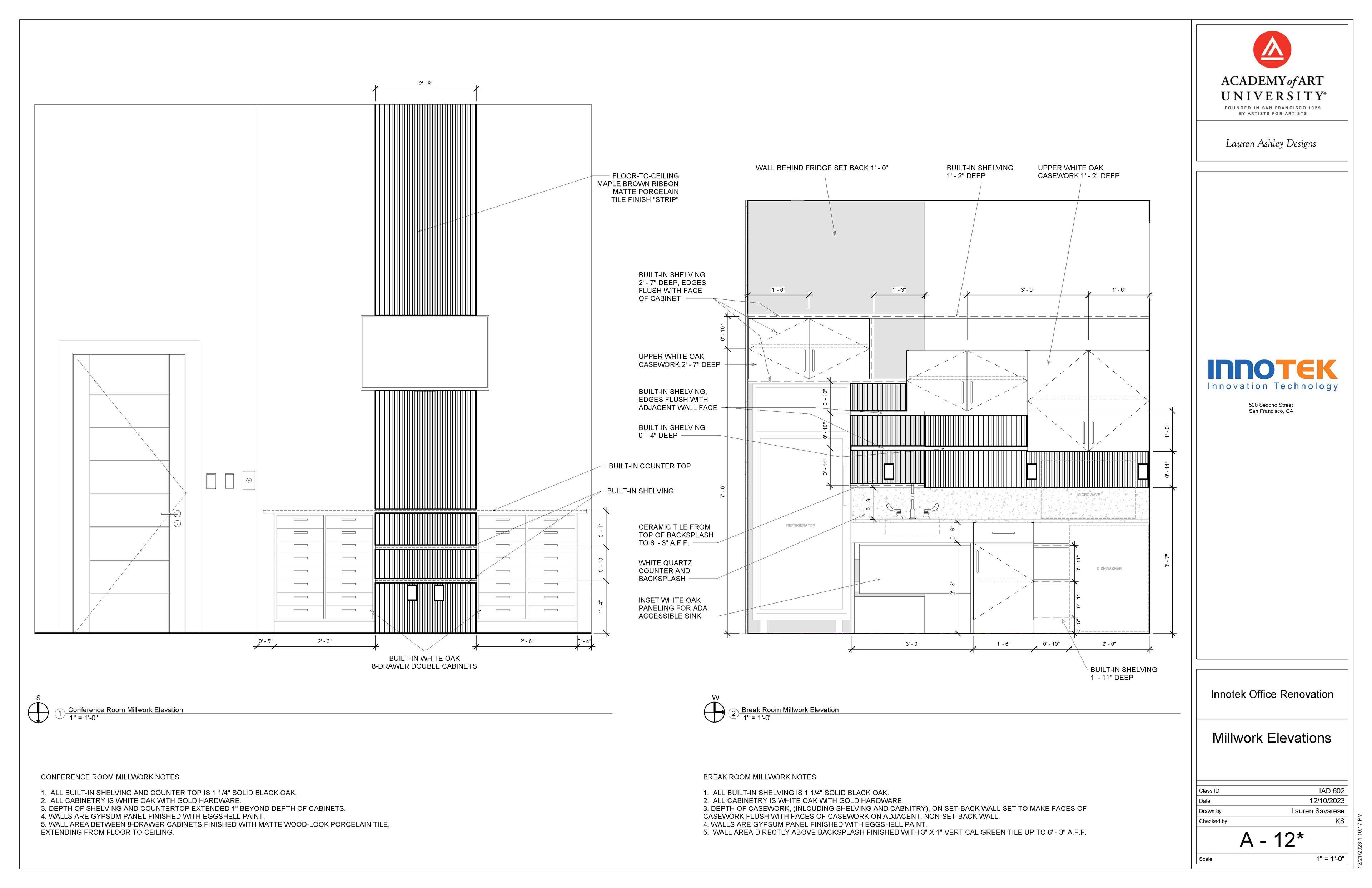
This research and my detail inspirations can be seen below, followed by the final door and ceiling detail. A casework detail of the break room kitchenette was also required.
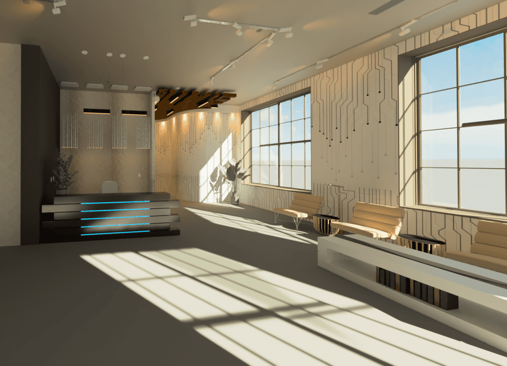
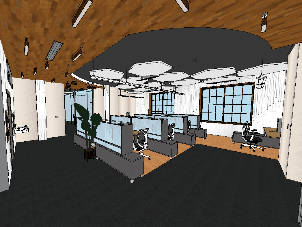
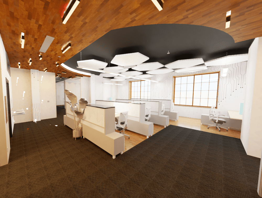
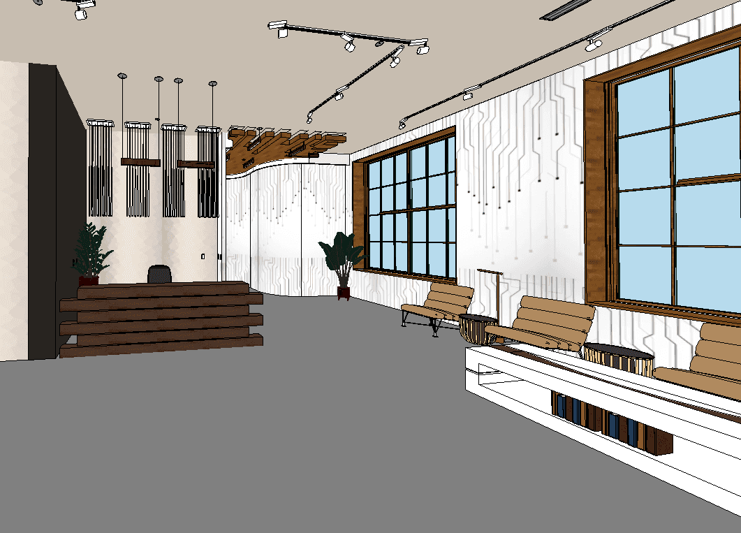
3D Model Snapshots
Though renders were unnecessary for this project, I did take these two snapshots of the interior of the Revit model I built, and quickly rendered them within Revit. The open work area at the center of the floorplan on Level 2 is seen at right. The respective render, as well as a snapshot and render of the lobby/reception area on Level 1, is seen below.
Results
The project was a great success. The client's programmable requirements were all met, the design evokes a technologically driven environment becoming of a tech company, and the space's code compliance is rock solid.
My progress in contract document creation was significant, and most importantly, I gained a new sense of confidence in designing a project from the true beginning (site/zone research and occupancy calculations) as well as great comfort in knowing how to ensure my designs are always up to code.